F125B experiences with the PDI
Point Diffraction Interferometer - not usefull in all cases
Dear Massimo,
this would be the answer to your email.
In optical Shop Testing, Second Edition, from Daniel Malacara, a Wiley-Interscience Publication, you just can find a
short note on page 112: "... the so called point diffraction interferometer, first decribed by Linnik in 1933, rediscovered
by Smart and Strong 1972, and more fully developed by Smart and Steel 1975. [...] To produce an interferogramm with
good contrast, the wave passing through the film and the diffracted spherical wave should have the same amplitude.
This is controlled by means of tzhe filter transmittance and the pinhole or disc size."
Some of the astronomical guys handle this as a great invention, but it is a poor possibility to get fringes map. Its not
usefull for many applications.
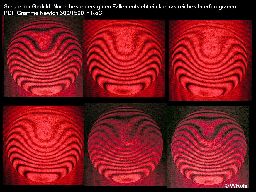
- It just works if you need newton rings of an optic as link01 shows
- it works in RoC with an f/10 light cone in testing a parabola, but just with a definite number of fringes, there is no
continous contrast, if you need more fringes. It changes between sharp fringes map by a definite low number and
becomes unsharp with no contrast with a higher number of fringes.
- it works with just a few numbers at a sphere and it becomes very unsharp, if you want more straight fringes.
- the fringes map in total seemed to be not a circle: with a sphere, this would be no problem, but in RoC this is a problem.
- the PDI works with a small light cone f/10 > x > f/20
If you start with experiences you need a bright light source like a laser diode without the small lens. With my normal
pinhole light, it wasnt bright enough and it didnt work. I guess the density should be lower.
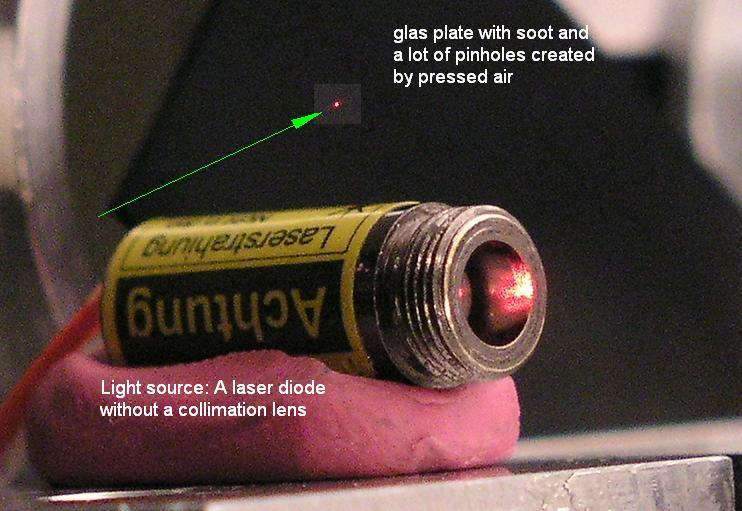
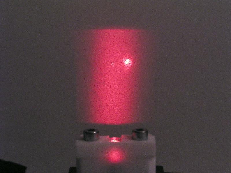
But this diode is producing not an ideal light point. Iis just a light beam as the foto shows. The best results you get,
if you align this vertical.
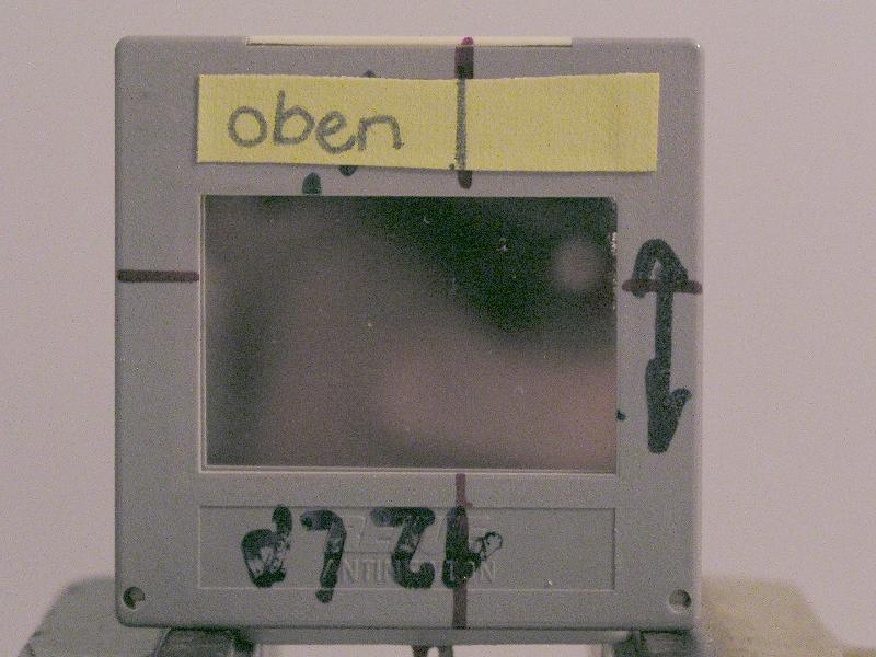
The next you need is the semitransparent film or overcated glas plate, as thinner as better. I experimented with
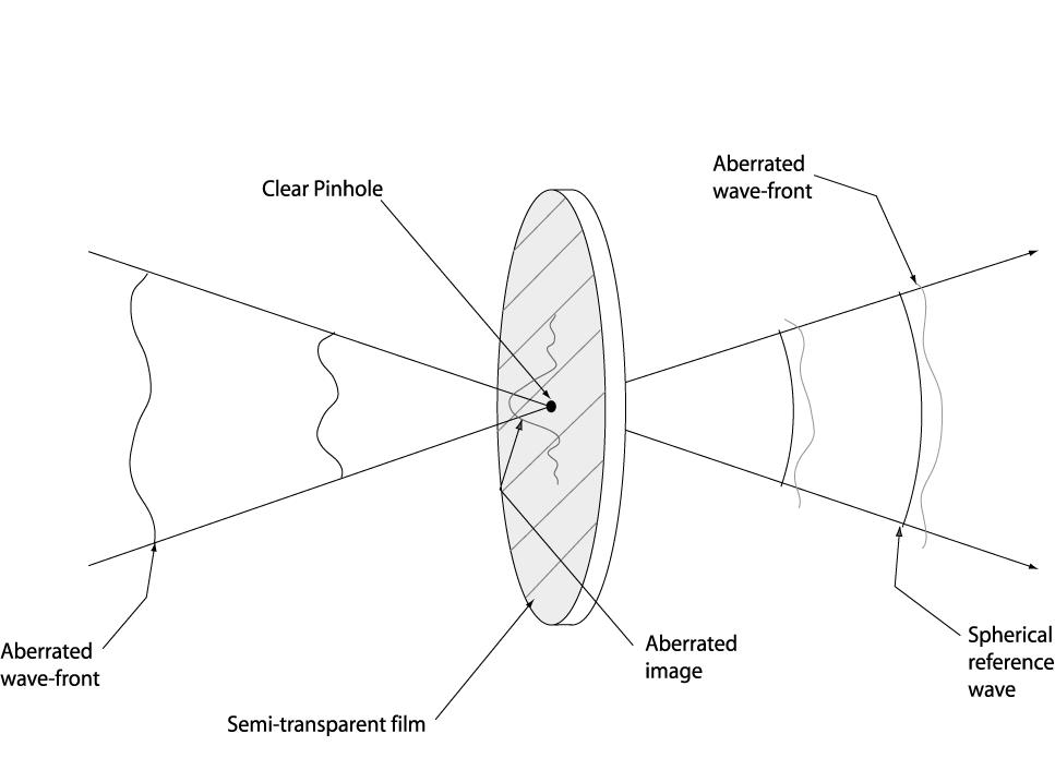
soot plates at first, later with a 1 micron gold foil. Dont forget, the overcoating should show to the in coming wave
front, as the scetch shows.
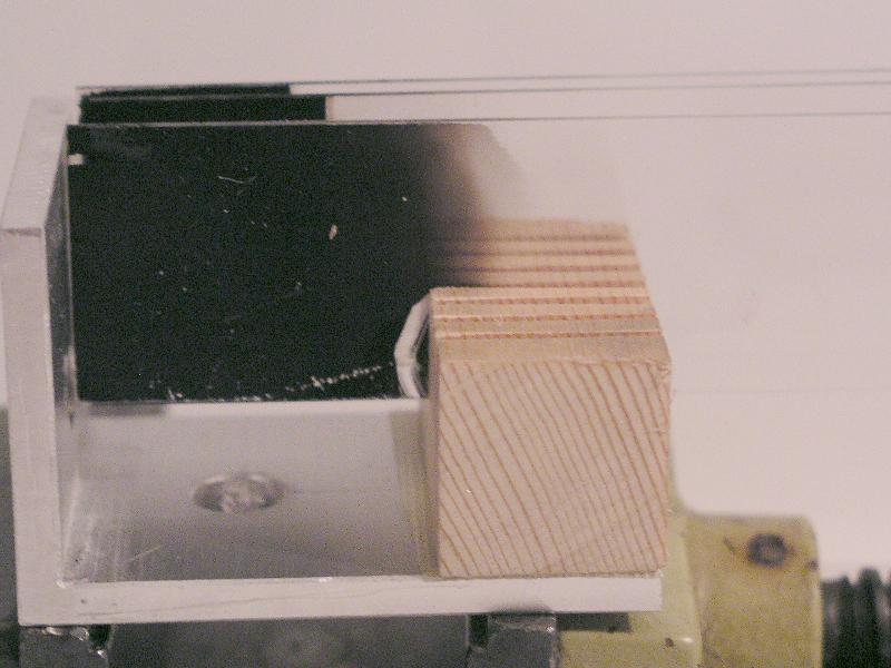
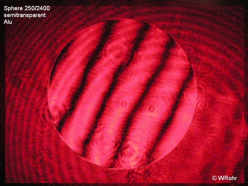
and later with semitransparent Alu overcoated plates, as the next foto shows.
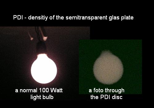
Now some about the density: If you see a 100 Watt light bulb very dark through that "filter", you got the right density.
All these overcoatings have small pinholes in the size of an Airy disc.
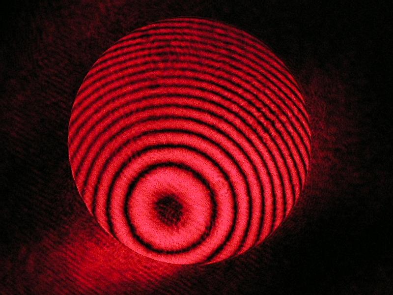
Now you want to get an interferogramm: Look at the first foto. The back coming light point is put in one of that
pinholes. But how easy you can find these one? Im looking for that pinholes extrafcal with a magnifying glas and
tten I move all to the focus. Out of focus you will see Newton rings with more or less contrast. And these fringes
are mostly with full contrast.
But if you start getting the fringes straight, suddenly the contrast becomes very low. And it varies between sharp
and unsharp fringes maps.
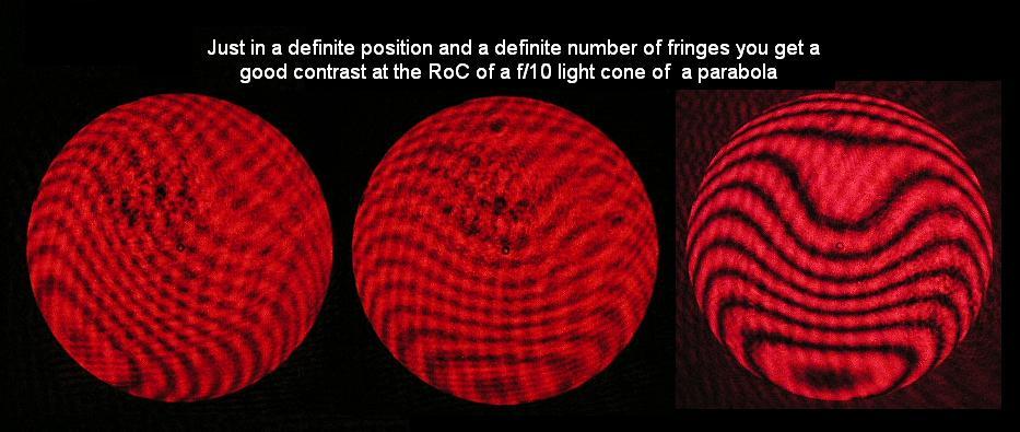
This is tricky to calculate it and you often think about it, does it show a correct result or not.
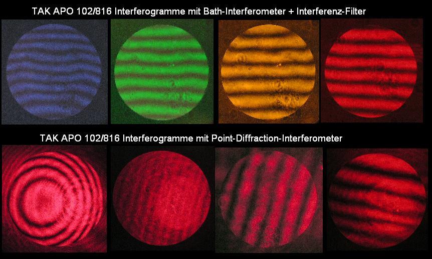
Its the same problem, if youll test a sphere 250/2400. You can get a map with contrast but just few fringes, or the
contrast decrease.
So I think, this PDI is usefull for Newton rings as the Link01 shows, and usefull for RoC-testing with a few fringes and a
small f/10 light cone. But it is not an all round interferometer. And this could be the reason, that the PDI is not as
interesting since 1933 as the other interferometer types.
Link04;