E030 Aligning a Cassegrain System in front of a Flat Cassegrain- Zentrierung- Setup
Aligning a Cassegrain System in front of a Flat
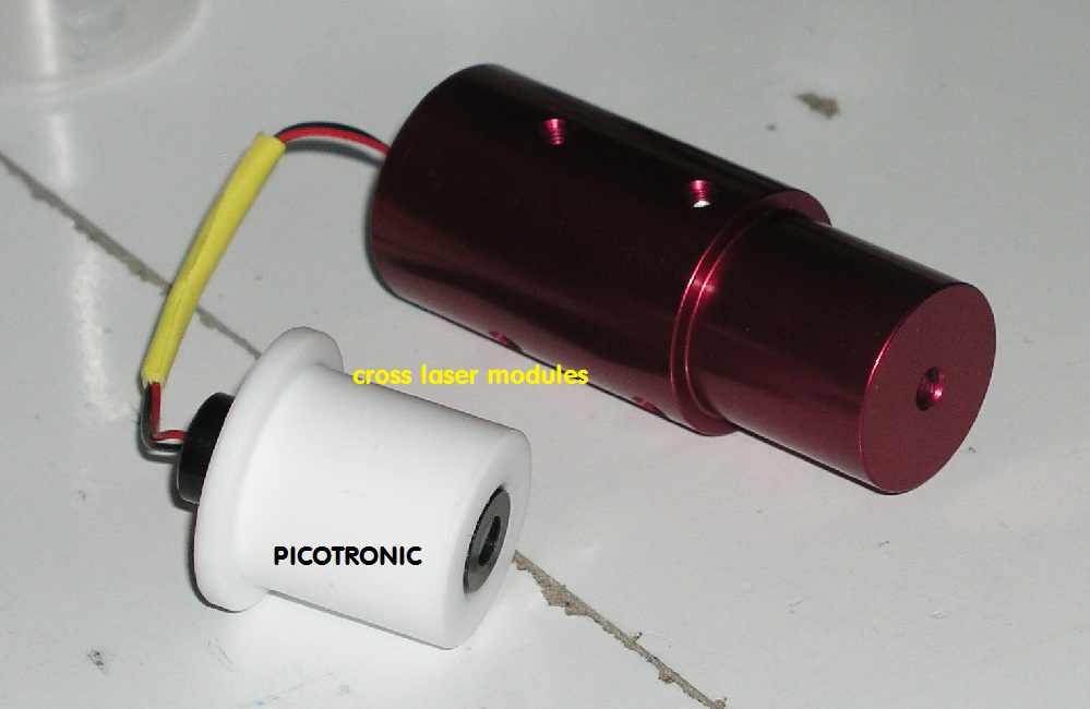
cross laser module: Picotronic

Quote:
Preface
A two mirror system e.g. SC, Cassegrain or RC has a definite distance of the two mirrors, a definite focus plane and both mirrors are
exact on optical axis. There are some ways to bring them there. After this, you can add a collimation flat behind the secondary or
behind the two-mirrors-system for total reflecting the outcoming parallel beam of that system. This would be the testing setup for this.
A) You can start with the main mirror (primary). In the hole of the primary you insert a laser module, laser pointer or aligned laser system. This should
be exact vertical to the mirrors surface. You can realise it by a bearing bush with a ring what touches the mirrors surface and runs with optical axis.
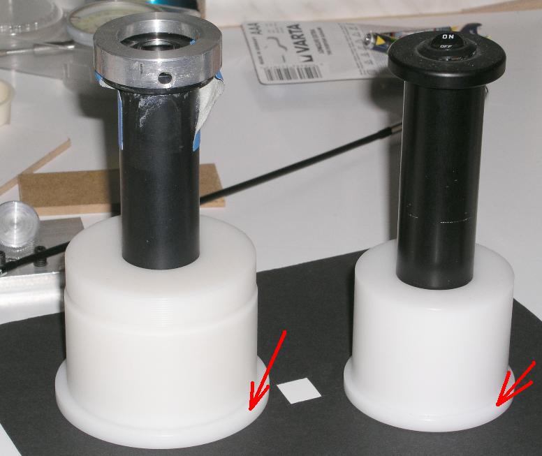
With a aligned laser system, as this foto shows, you can produce this bearing bush via a lathe with synthetic material, as the foto shows. Note the red
arrows, this would be the contact ring. In a second step, you align the secondary what is fixed at a normal spider. Now the two mirrors system will
be aligned back with the laser. At last you remove the laser from the primary and align the collimation flat to this system with a divergent bright light
source at the focus. At the focus you can test this system in different ways. With Ronchi, Foucault or interferometer.
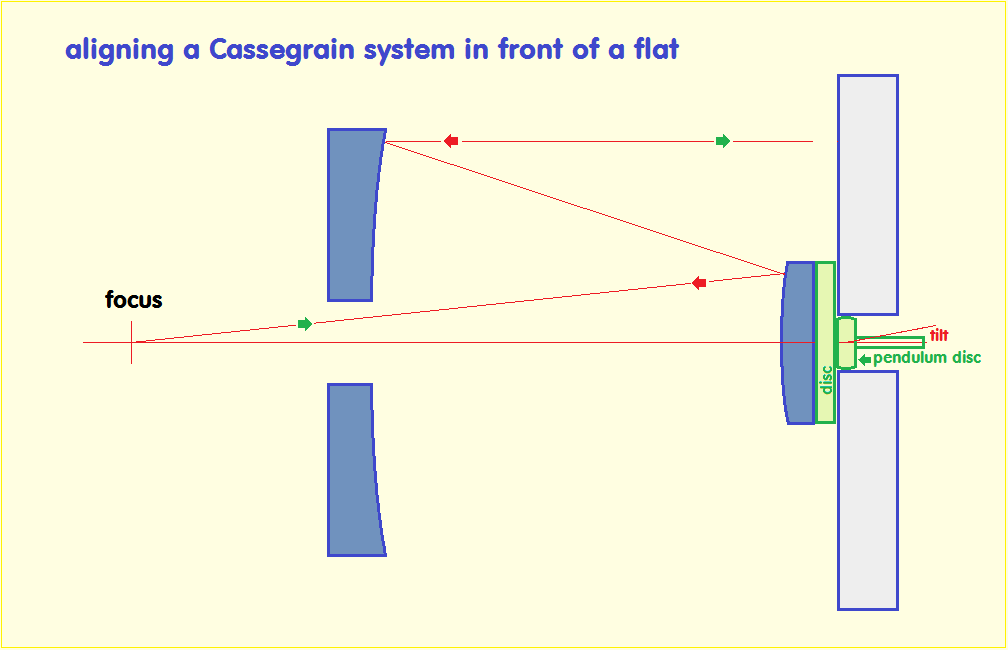
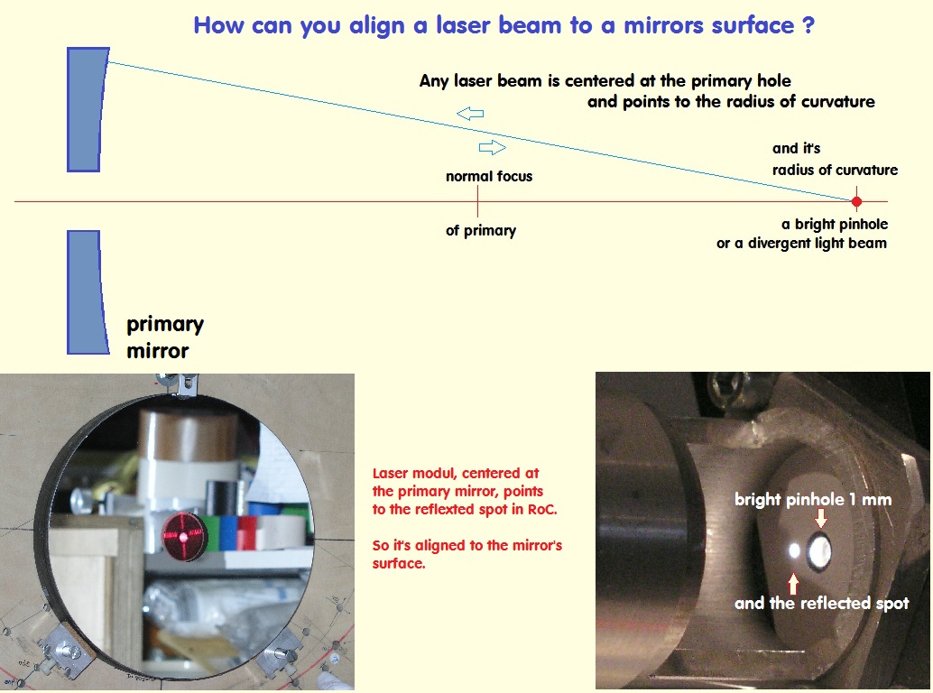
A1) The laser beam or the cross laser at the primary mirror you also can align, if you insert at the radius of curvatury a bright divergent pinhole beam.
Note this: http://rohr.aiax.de/CassZ_20.jpgThis would be the mirrors center, and the center of any laser module have to point there. Note that foto.
B) To avoid a spider for the secondary and if your flat has a hole, there you can insert the secondary, as the following report shows. Now you also
need the primary mirror with it's concentric laser beam. For the collimation flat, there you need a small flat, that surface has to coninside with the
surface of the big flat, as this foto shows. (kleiner Planspiegel) This you can realise with a bearing bush, too. Note the foto.
Later you remove the small flat and insert the secondary, and then you align this one back to the primary mirror without moving the collimation flat.
C) You also can use a cross laser module. You also start with it at the primary and there it has to run with the optical axis. This condition is very
important. You can put a bright pinhole at mirrors radius of curvature, and there have to point the center of the cross laser modul. Then you
align the big flat mirror with the cross laser and at last you insert the secondary, as my report shows later. Note that foto.
.
Neues GSO 8" f/8 RC - Ritchey-Crétien 203/1624 ___ Hauptspiegel-Zentrierung beim Cassegrain-System Abrollverfahren
GSO 8" RC - Hauptspiegel-Zentrierung über Laser-Beam Laser Pointer, 8-inch GSO RC Abrollverfahren

This was a report to check a Cassegrain-System in front of a flat. Both mirrors were aluminized. For this it's easier to align this setup.
In principle this should work with uncoated mirrors, too. The mirrors distance define the fokus plane, this is one of the problem. The
other one is the tipping of one of the components and at last, how bright the light source are. The best one for that would be a bright
laser module with an addional eyepiece, or any cross laser module. With this setup you will arrange different tests: Ronchi, Foucault,
interferogramms.
This was a report in 2010 with this problem, aligning a Cassegrain System in front of a Flat. The main mirror shows a lot of astigmatism, and so
you should test at first the optical quality of it. The flat I used has a drilled hole of 80 mm. There you can insert the secondary mirror and
align this one from the back as the foto shows at right.
http://www.astro-foren.de/showthread.php?p=49892#post49892
http://www.astro-foren.de/showthread.php?t=12248
Main mirror left - Secondary in the middle and the aligning system for Secondary in the back of the flat
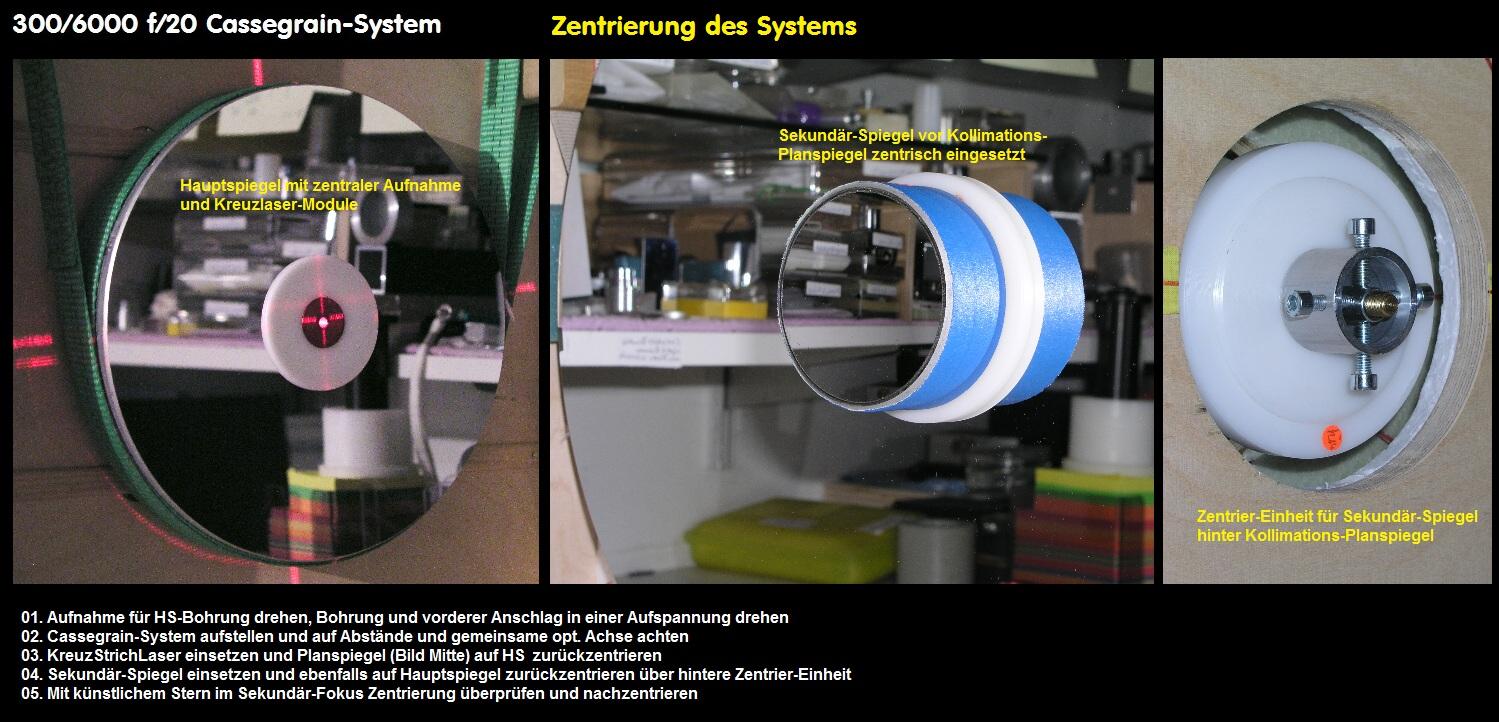
http://rohr.aiax.de/CassZ_20.jpg
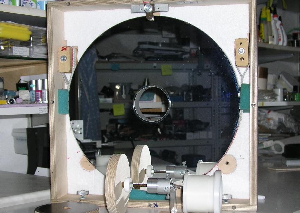
This shows the setup of a Cassegrain-system. It's better to use a flat with a drilled hole, so you can insert there the secondary and align it there on the back.
Without a hole you have more problems for a setup.
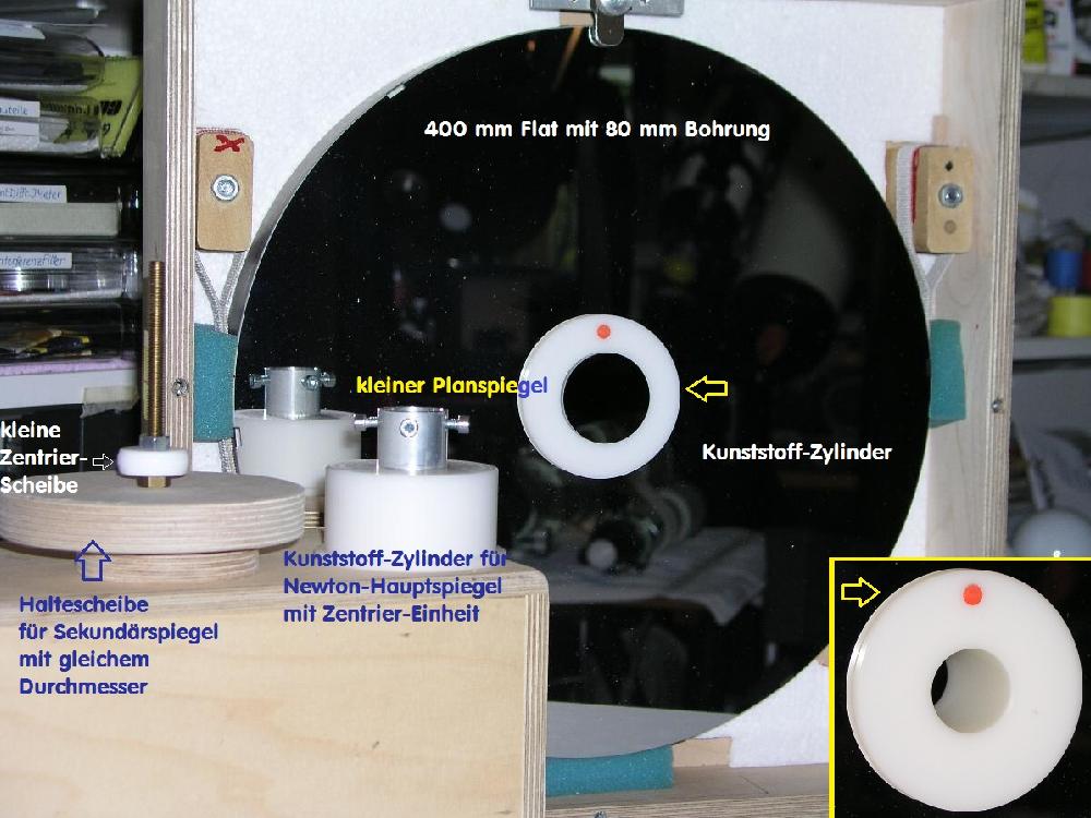
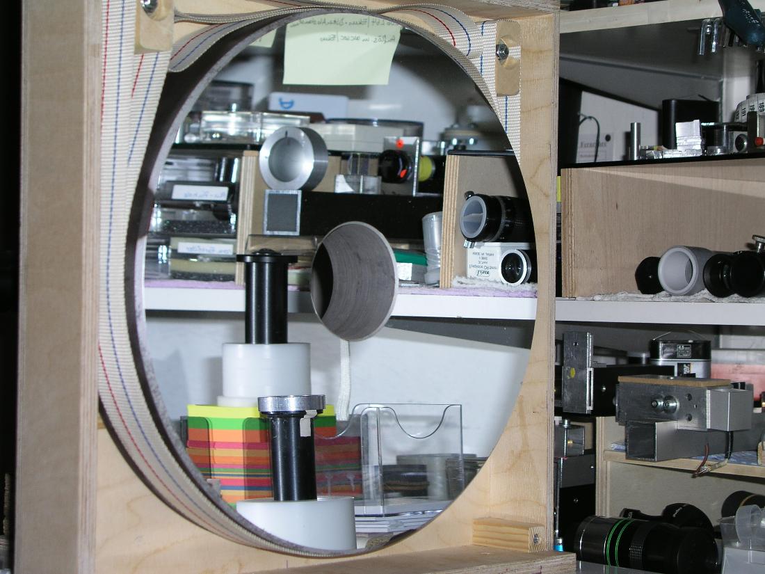
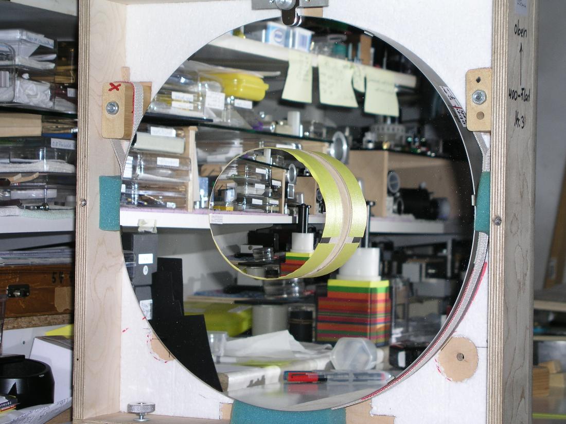
I use a flat with 400 mm diameter and 80 mm hole. In this hole I insert different tools: A small flat mirror, to bring the large flat mirror on optical axis.
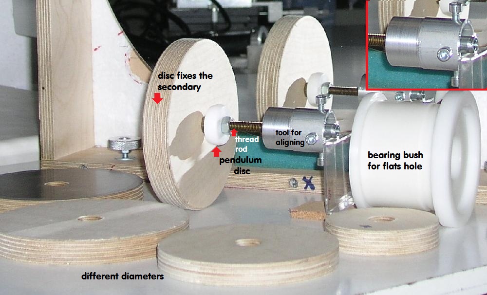
Some tools to fix a Cassegrain secondary on the "Haltescheibe", a small 1 1/4 inch disc for tilting the secondary with a longer thread rod on the flats back
as it shown on the first foto with "Kunststoff-Zylinder". Normally I insert a laser pointer for aligning a Newton mirror for an autocollimation test.
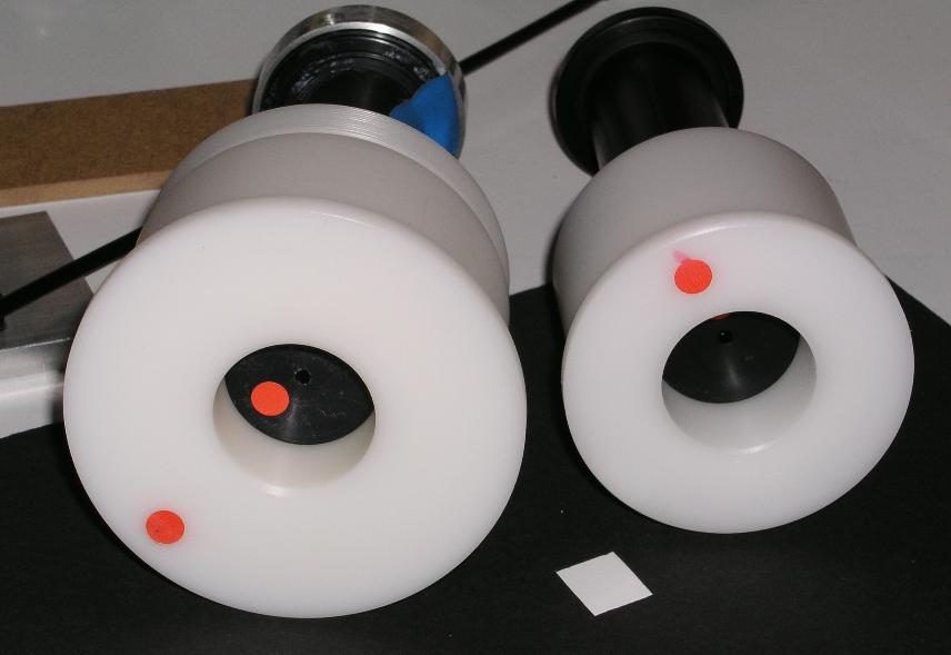
This shows the wooden disc what fixes the secondary with the same diameter. A thread rod is bonding the pendulum disc from plastic. This is
inserted in the plastic bearing bush with a tool for aligning this unit.
This is the flat with 400 diameter and a 80 mm hole.
This shows, how you can align a laser modul at the primaries hole:
Now some cross laser modules
And this shows, how they work
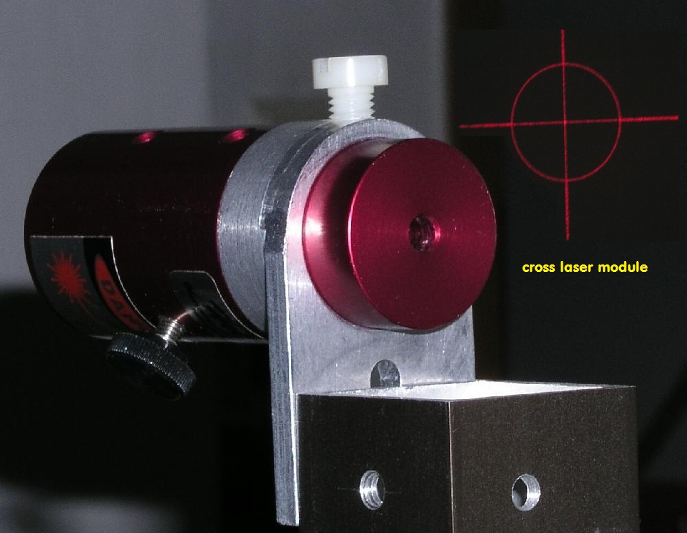
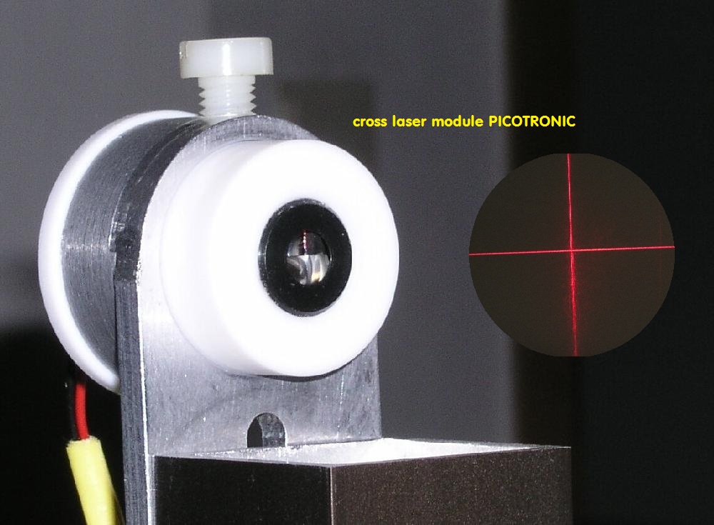
But there is a third possibiliy for aligning this set up:
01. With the normal laser pointer, you align at first the secondary on optical axis. (The mirrors distance must be correct.)
02. Then you add the eyepiece on the laser and so you get a divergent light beam. With this, it should be possible, to align the main mirror and at last
03. the flat
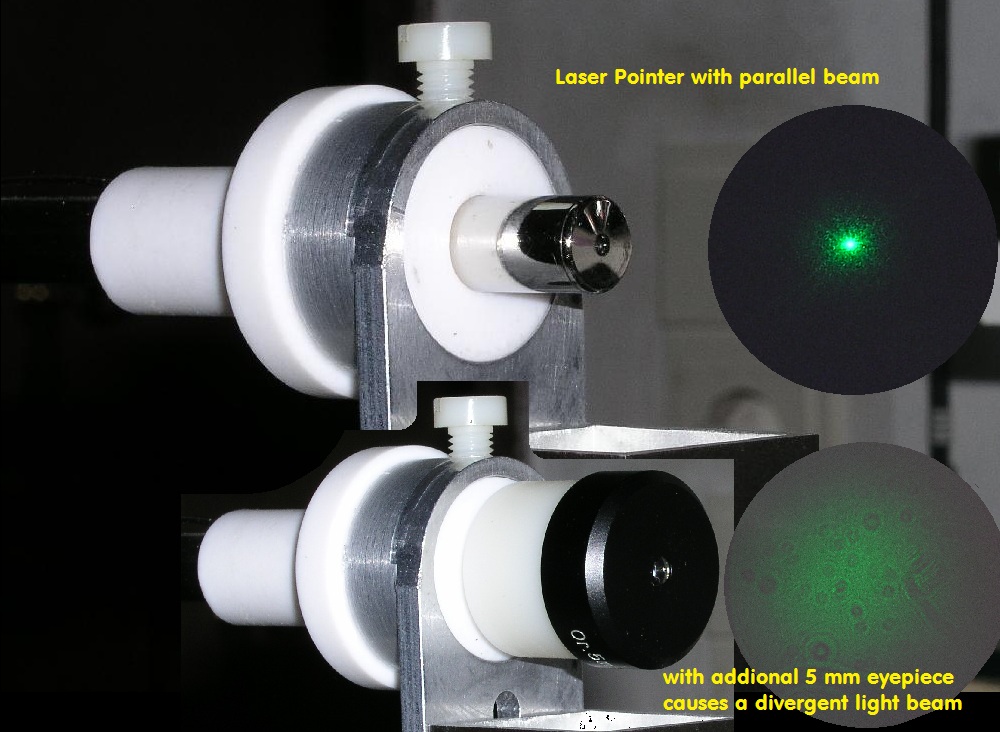
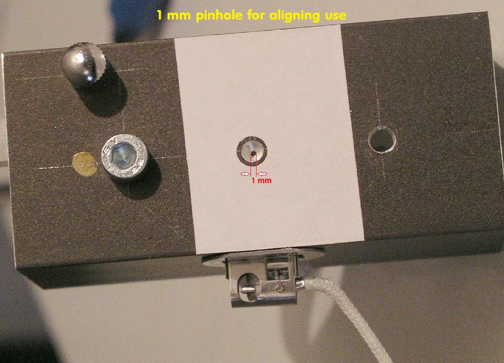
A bright light source with 1 mm diameter and a car light bulb could be another option.
This is the wooden box what keeps the primary mirror, it has a hole and the box, too: http://www.astro-foren.de/showthread.php?t=12248
This are the plastic cylinders what keeps the laser module. They are made for different diameters. For every primary I have to produce a new one !
Note the arrows! This is running with the mirrors surface.
And this is the flat with the secondary mirror.
##################################################################################
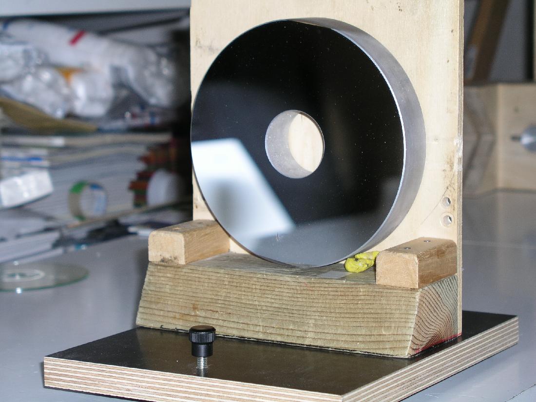
Zentrierung des Primär-Spiegels auf der opt. Achse
Zweispiegel-Systeme oder aber nur dessen Primär-Spiegel, lassen sich auf folgende Arten zentrieren. Für fotografische Benutzung sollte dieses Verfahren
ausreichend sein. Das Bild zeigt den Primär-Spiegel eines Cassegrain-Systems mit einem Krümmungsradius (RoC) von ca. 2000 mm. Der Hauptspiegel hat
notwendigerweise eine Bohrung, durch die man später durchschaut von der Rückseite dieses Spiegels. Man kann nun entweder in diese Bohrung selbst
einen Laser-Pointer einsetzen, der dann - justierbar - auf den Punkt in RoC gerichtet werden muß, oder aber man startet über dem Krümmungsmittel-
punkt (RoC) das Verfahren, wie die folgenden Bilder zeigen.
Der Spiegel und seine Lagerung müssen verkippbar sein - deshalb die untere Stellschraube für die Höhe - verdrehbar ist diese Lagerung ohnehin.
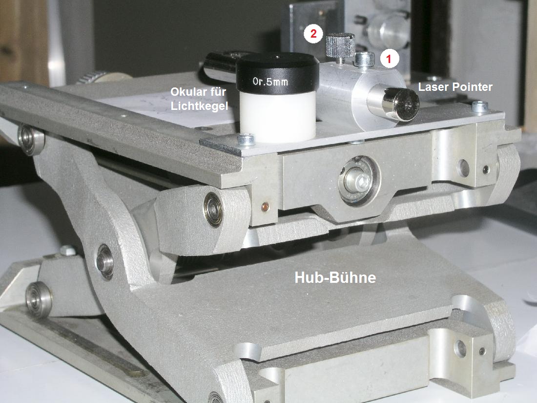
Auf seiten der Lichtquelle sieht man nun den Laser-Pointer in seiner eindeutigen Lagerung: Die vordere Schraube ( Nr. 1) hält ihn in der Buchse fest, mit der hinteren
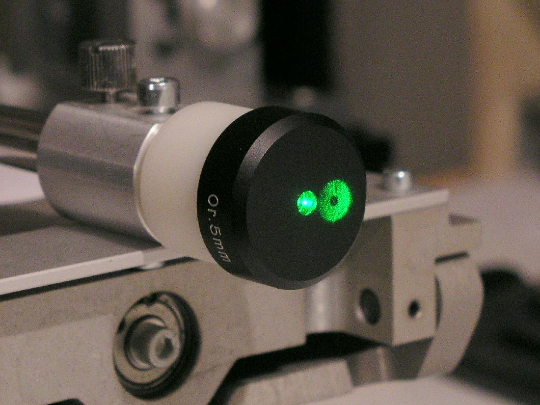
gerändelten Schraube ( Nr. 2 ) kann man ihn ein- und ausschalten. Links daneben erkennt man das 5 mm Okular, das mit einer Halterung versehen ist, damit man es
auf den Laser-Pointer im zweiten Schritt aufstecken kann. Das Ganze ist auf einer Hub-Bühne aufgesetzt, damit man auch dort die Höhe fein verstellen kann.
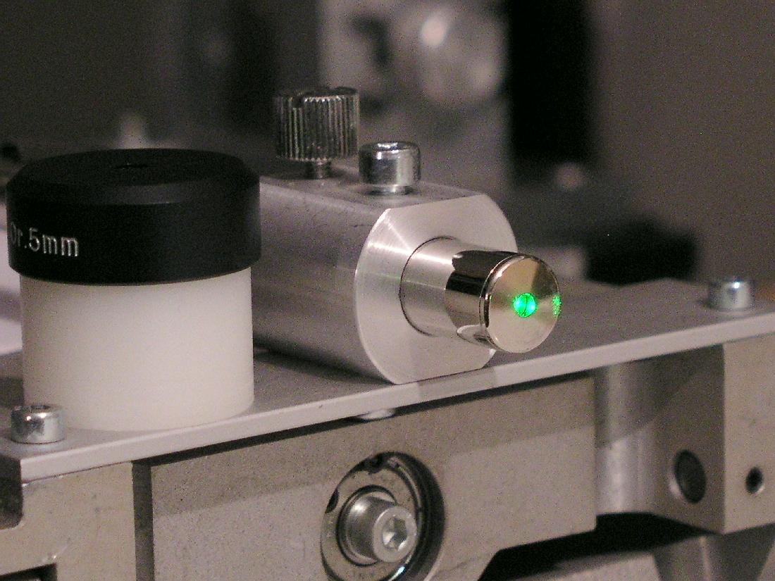
Nun schaltet man den Laser ein, und richtet ihn auf das Zentrum des vorher gezeigten Primär-Spiegels.
Das erkennt man auf der Spiegelseite: Der Laser-Pointer trifft durch die Bohrung des Hauptspiegels die Rückseite meiner Holz-Lagerung.
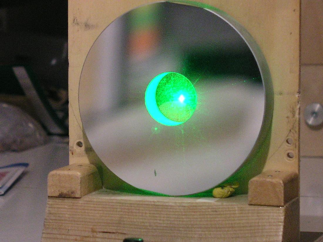
Nach der Ausrichtung des Laser-Parallel-Bündels a) zum Hauptspiegel und b) zurück zum Laser-Pointer selbst, steckt man nun das 5 mm Okular auf den Laser
und erzeugt aus dem Parallel-Bündel einen Lichtkegel. Weil die Laser-Lichtquelle ziemlich genau im Krümmungsmittelpunkt ( 2 000 mm ) des Primär-Spiegel ist,
entsteht so über das divergente Bündel - vom Okular erzeugt, der Reflex vom Hauptspiegel. Der Sichtbarkeit wegen ein bißchen nach hinten verschoben.
Wenn beide Bündel konzentrisch zusammenfallen, dann stellt das Parallel-Bündel des Laser-Pointers die opt. Achse des Primär- oder Hauptspiegels dar. Damit
läßt sich bereits überprüfen, ob bei einem fotografischen System der Hauptspiegel exakt zur Fokus-Ebene ausgerichtet ist.
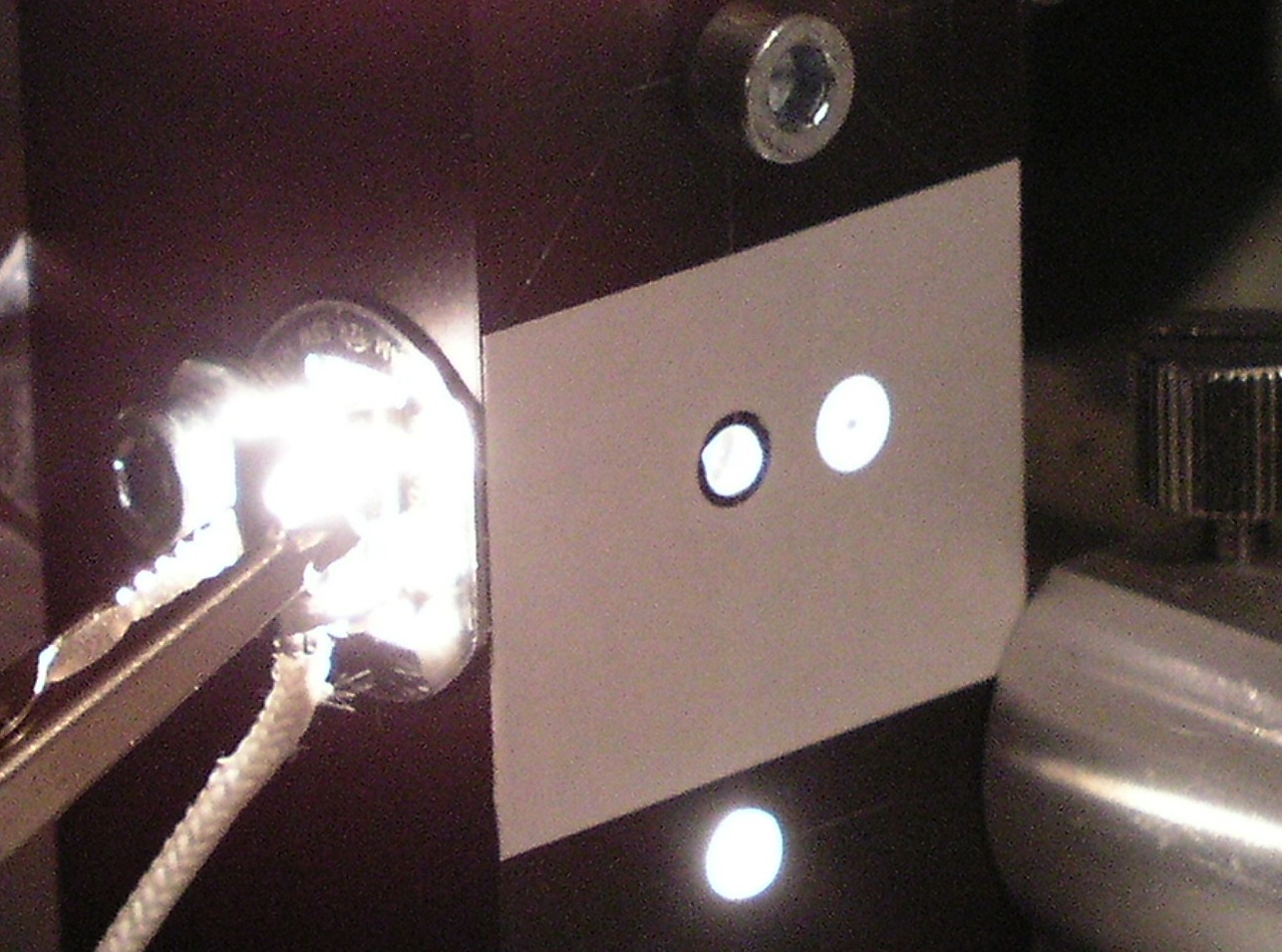
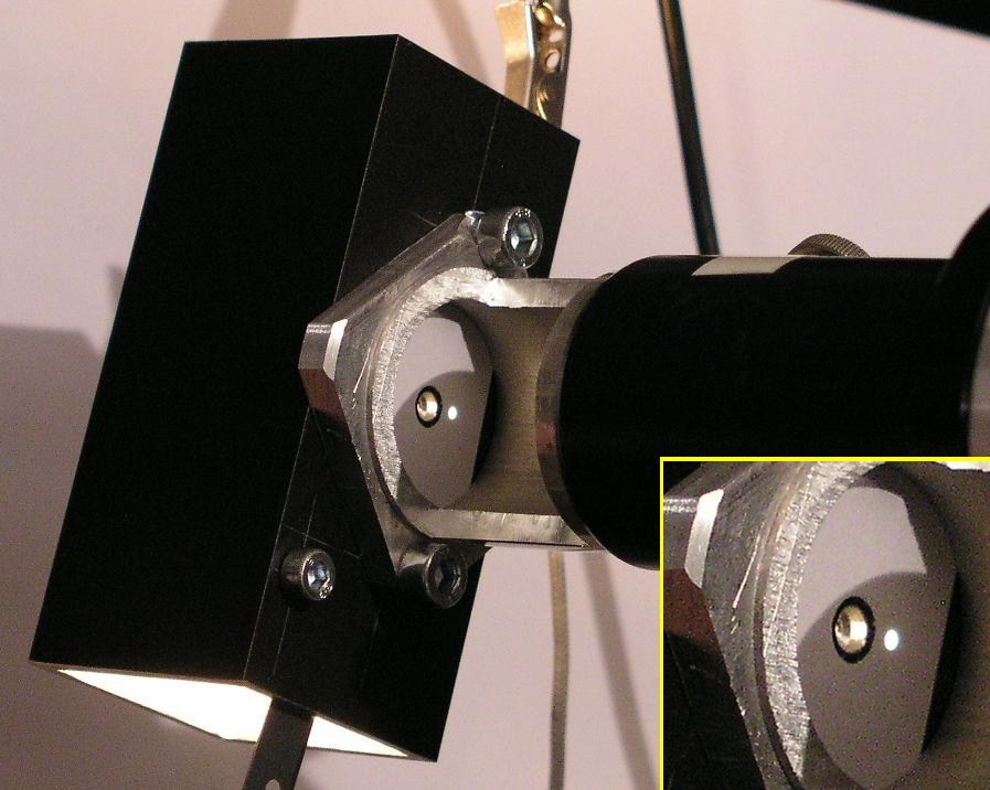
Eine andere Möglichkeit bietet eine helle Pinhol mit Durchmesser 1 mm. Die Lichtquelle bildet ein Auto-Scheinwerfer-Birnchen in dem Alu-Rechteckrohr, in das die
1mm Pinhole gebohrt worden ist. Außerhalb erkennt man die weiße ProjektionsFläche.
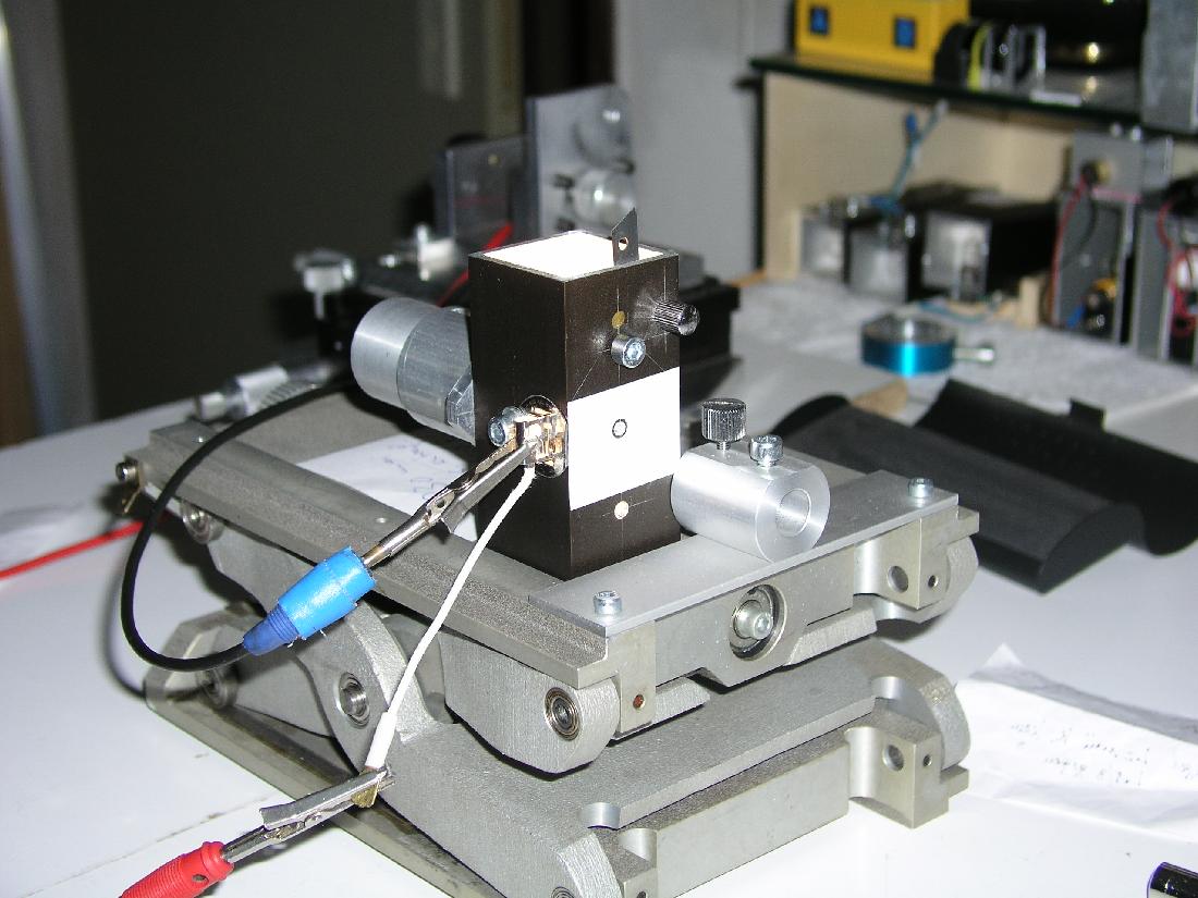
Auch hier stellt man diese Lichtquelle in den Krümmungsmittelpunkt und justiert Spiegel und Lichtquelle so, daß man den Reflex-Punkt auf diese Projektionfläche
bekommt.
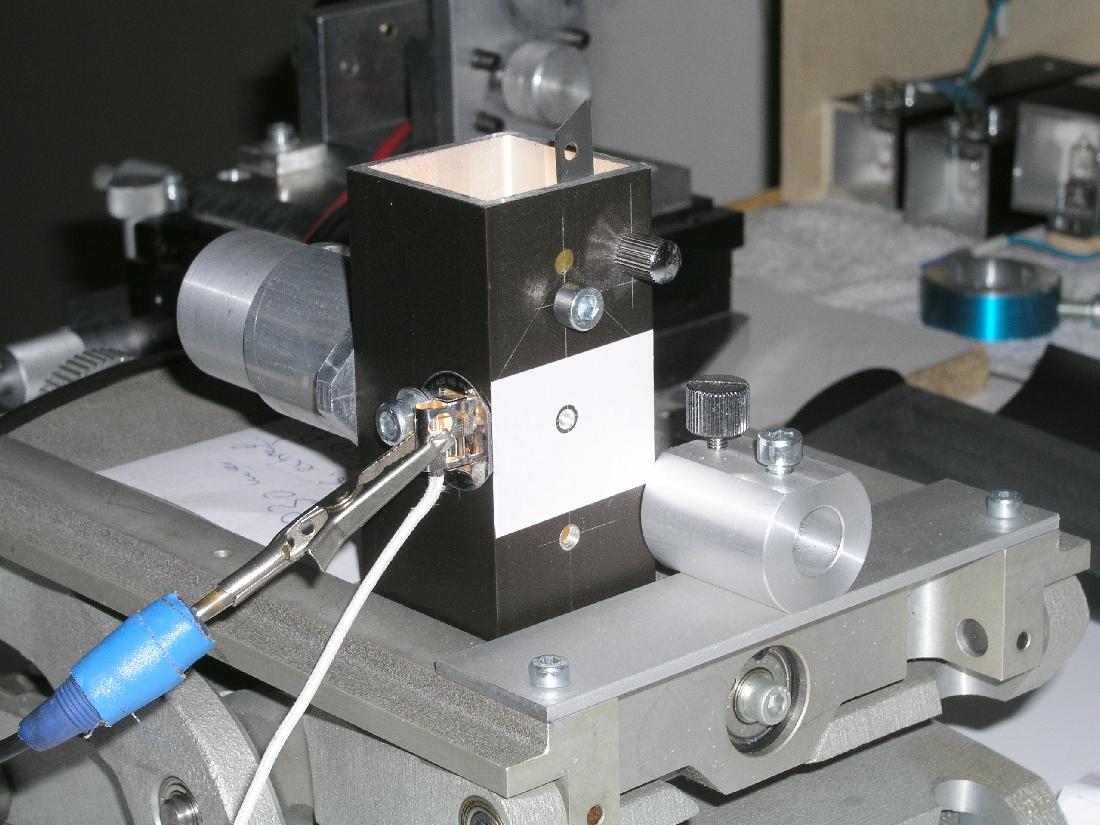
Die Situation noch etwas vergrößert . . .
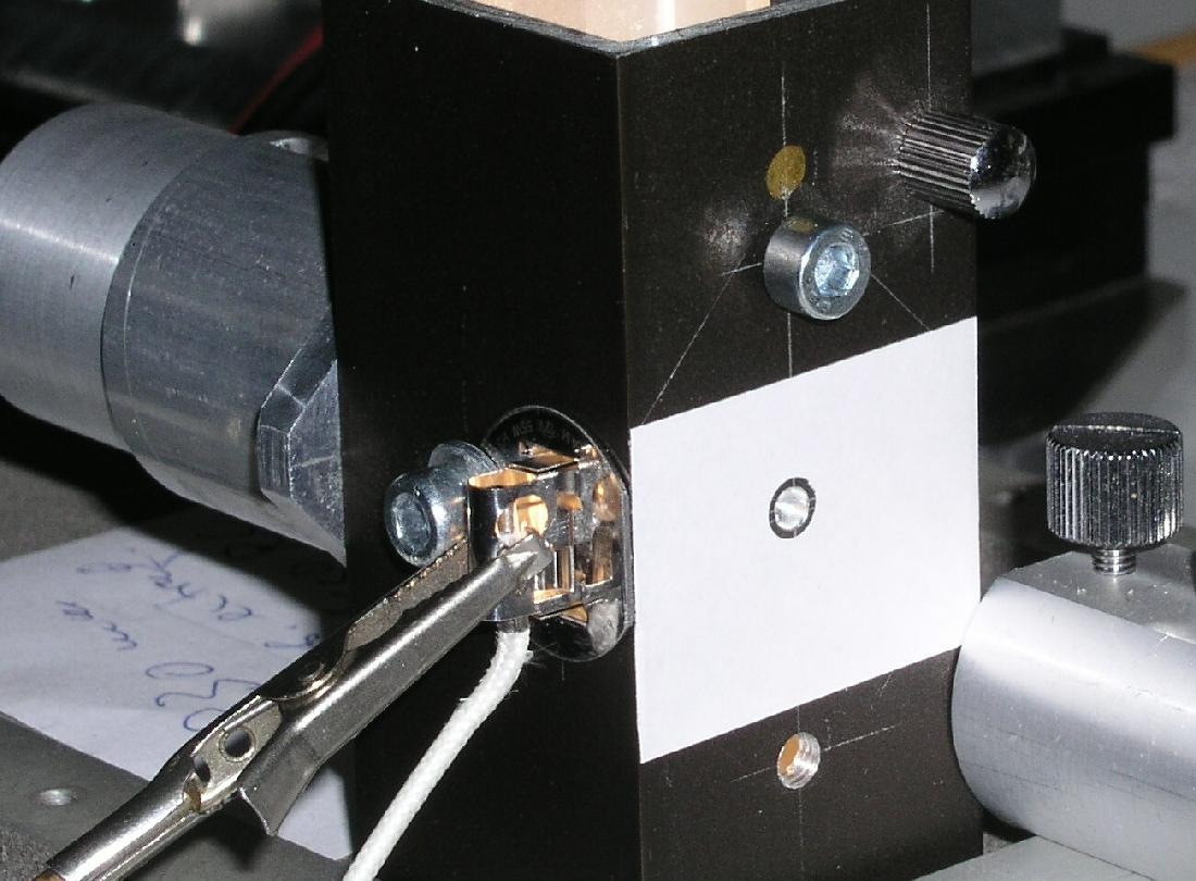
und nun ebenfalls leicht versetzt neben der Pinhole die Reflex-Scheibe des Primär-Spiegels im Krümmungsmittelpunkt. Auch damit läßt sich die opt. Achse darstellen,
die gebildet wird über die Mitte der Primärspiegel-Bohrung und der Mitte der 1 mm Pinhole. Je nach Erfordernis läßt sich dieser Testaufbau variieren.
Der erste Bericht oben zeigt bereits einige weitere Möglichkeiten.
